|
|
Enlarges the size of the IEEE Symbol currently being placed/moved |
||
|
|
Switch to the next enabled layer |
||
|
|
Switch to the next enabled (and rule-permitted) layer, dropping a via |
||
|
or
|
|||
|
or
|
|||
|
|
Change the current layer for the design to the next layer in the Layers list |
||
|
|
Make the next available analysis chart the current chart in the Waveform Analysis window |
||
|
|
Extend a selection to the beginning of the current line from the current cursor position |
||
|
|
Add a new comment thread to a specified point in the active document. Before you can start using the comment feature, ensure that you have opened (checked out) a Managed Project and are working on one of its source schematic documents |
||
|
|
Reduces the size of the IEEE Symbol currently being placed/moved |
||
|
|
Toggle the display of the Difference Map Overlay in the main design workspace On or Off |
||
|
|
Switch to the previous enabled layer |
||
|
|
Add a new comment thread to a specified point in the active document. Before you can start using the comment feature, ensure that you have opened (checked out) a Managed Project and are working on its PCB document |
||
|
|
Switch to the previous enabled (and rule-permitted) layer, dropping a via |
||
|
or
|
|||
|
or
|
|||
|
|
Rotate the 3D body object being placed/moved clockwise around the model's X-axis by 90° |
||
|
|
Rotate the view of the board (or component) in 3D 30 degrees down |
||
|
|
Change the current layer for the design to the previous layer in the Layers list |
||
|
|
Make the previous available analysis chart the current chart in the Waveform Analysis window |
||
|
|
Open the Tool Palette panel |
||
|
|
Choose the required track width from available predefined favorite routing widths in the Track mode of the Properties panel |
||
|
|
Choose the required track width from available predefined favorite routing widths in the Favorite Interactive Routing Widths dialog |
||
|
|
Choose the required track width from available predefined favorite routing widths in the Track mode of the Properties panel |
||
|
or
|
|||
|
|
Rotate the 3D body object being placed/moved clockwise around the model's Y-axis by 90° |
||
|
|
Rotate the view of the board (or component) in 3D 30 degrees right |
||
|
|
Run the current script up to the line where the text cursor is currently positioned, then pause |
||
|
|
Rotate the 3D body object being placed/moved counterclockwise around the model's X-axis by 90° |
||
|
|
Rotate the view of the board (or component) in 3D 30 degrees up |
||
|
|
Access the Board Insight pop-up, listing all components and/or net objects currently under the cursor |
||
|
|
Converts a closed polyline to a solid polygon region |
||
|
|
Open the script Evaluate dialog to see the current value (result) of the expression located at the cursor |
||
| + |
(Drag and drop from Windows Explorer into Altium Designer) Open a document, project, or design workspace |
||
| + |
(click on an object, hold and drag) Move the single object currently under the cursor (or group of selected objects if the object is part of that selection) |
||
| + |
(Click (away from objects), hold and drag (left-to-right)) Select all objects that fall completely within the bounds of the selection area |
||
| + |
(Click (away from objects), hold and drag (right-to-left)) Select all objects that fall completely inside the selection area or are touched by its boundary |
||
| + |
(click an object, hold and drag) Move the single object currently under the cursor (or group of selected objects if the object is part of that selection) |
||
| + |
On a via in a stack of vias, use to move the entire stack to a new location |
||
| + |
One or more selected applicable (printable) outputs into the Hard Copy region to create a new Print Job. The output(s) will automatically be linked |
||
| + |
One or more selected applicable outputs into the Output Containers region to create a new PDF output container. The output(s) will automatically be linked |
||
| + |
One or more selected PCB3D Video outputs into the Output Containers region to create a new Video output container. The output(s) will automatically be linked |
||
| + |
One or more selected applicable outputs into the Output Containers region to create a new Folder Structure output container. The output(s) will automatically be linked |
||
|
|
Obtain information with respect to a single selected net in the current document |
||
| + |
Full control of text selection |
||
|
|
Enter the desired bus routing |
||
|
|
Cycle through the defined Width-Gap value pairings available for the differential pair being routed, through the applicable Differential Pairs Routing rule (Min Width-Min Gap --> Preferred Width-Preferred Gap --> Max Width-Max Gap) |
||
|
|
Increase the spacing between neighboring routes |
||
|
|
Toggle the display of the current film box |
||
|
|
Execute the current function after all required objects involved in the function have been selected |
||
|
|
Open the Object Inspector panel |
||
|
|
Toggle the display of the SCH List panel or the SCHLIB List panel accordingly |
||
|
|
Toggle the Heads Up Display on or off |
||
|
|
Toggle on/off whether the cursor on a grid will snap to the active workspace grid. Once enabled, the cursor will pull or snap to the nearest snap group location |
||
|
|
Toggle the display of the PCB List panel or the PCBLIB List panel accordingly |
||
|
|
Toggle the highlighting of objects based on the current Dcode. In this way, you can interrogate exactly wit which objects a particular Dcode is associated |
||
|
|
(drag from right to left) To select all connections touched by the dragged rectangle |
||
|
|
Full control of column selection |
||
|
|
Toggle the 3D model visibility in the current PCB document |
||
Advertisement |
|||
|
|
Converts a closed polyline to a CutOut polygon |
||
|
|
Zoom-in, relative to the current cursor location and in progressively smaller steps |
||
|
|
Extend a selection by one page up from the current cursor position |
||
|
|
Zoom-out, relative to the current cursor location and in progressively larger steps |
||
|
|
Extend a selection by one page down from the current cursor position |
||
|
|
… to |
||
|
|
… to |
||
|
|
Change the view of the board (or component) in 3D so that you are looking at the board from the top side |
||
|
|
Change the view of the board (or component) in 3D so that you are looking at the board from an orthogonal perspective |
||
|
|
Open the Breakpoints panel |
||
|
|
Add a new comment thread to a defined area of the active document. Before you can start using the comment feature, ensure that you have opened (checked out) a Managed Project and are working on one of its source schematic documents |
||
|
|
Add a new comment thread to a defined area of the active document. Before you can start using the comment feature, ensure that you have opened (checked out) a Managed Project and are working on its PCB document |
||
|
|
Rotates the object being dragged clockwise. Rotation is in increments of 90° |
||
|
|
Extend a selection to the beginning of the current document from the current cursor position |
||
|
|
Extend a selection to the end of the current document from the current cursor position |
||
|
|
Activate the Method Parameters pop-up window |
||
|
|
Decrease the Standoff Height for the 3D body object being placed/moved by one Snap Grid unit |
||
|
|
Change the view of the board (or component) in 3D so that you are looking at the board from the left edge |
||
|
|
… to |
||
|
|
… to |
||
|
|
Open the Code Explorer panel |
||
|
|
(hold and drag) Drag the electrical object currently under the cursor while maintaining connectivity with other electrical objects |
||
|
|
On a via in a stack of vias, use to move just that via to a new location (and not the entire stack) |
||
|
|
Use to improve the quality of the selected routes by reducing the overall length and number of corners |
||
|
|
View and highlight all objects drawn with the current Dcode |
||
|
|
Change the view of the board (or component) in 3D so that you are looking at the board from the front side |
||
|
|
Access the Set Layers ON dialog in which you can specify which layers you wish to turn ON |
||
|
|
Extend a column selection by one line down from the current cursor position |
||
|
|
Extend a selection column by one column to the right of the current cursor position |
||
|
|
Extend a column selection by one line up from the current cursor position |
||
|
|
Extend a selection column by one column to the left of the current cursor position |
||
|
|
Increase the Standoff Height for the 3D body object being placed/moved by one Snap Grid unit |
||
|
|
Enable all selected outputs connecting them to the currently selected output container or print job |
||
| + |
(right click, hold and drag) Display the slider (panning) hand cursor then drag to move your view of the workspace |
||
| + |
Display the slider (panning) hand cursor then drag to move your view of the workspace |
||
|
|
Disable all selected outputs disconnecting them from the currently selected output container or print job |
||
|
|
Restore the active Multi-board document to its state previous to the last operation. Multiple levels of undo are supported |
||
|
|
Restore the current document to its state previous to the last operation. Multiple levels of undo are supported |
||
|
|
Switch the display of the PCB workspace to 2D Layout Mode and see the same location and orientation of the board as you switch. |
||
|
|
Align selected design objects by their left edges while maintaining adequate spacing in observance with applicable design rules |
||
|
|
Open the Watch List panel |
||
|
|
Toggle the display of the current document's editor between maximized and not maximized |
||
|
|
Switch the display of the PCB workspace to 3D Layout Mode and see the same location and orientation of the board as you switch. |
||
|
|
Toggle the display of the current document's editor between maximized and not maximized |
||
|
|
Converts a closed polyline to a solid polygon |
||
|
|
Extend a selection to the top of the current document window from the current cursor position |
||
|
|
Increase the radius of the arc (by 10mil/0.254mm increments) when in arc cornering placement mode |
||
|
or
|
|||
|
or
|
|||
|
or
|
|||
|
|
Extend a selection to the bottom of the current document window from the current cursor position |
||
|
|
Align selected design objects by their right edges while maintaining adequate spacing in observance with applicable design rules |
||
|
|
Move to the next message (down) in the Messages panel and cross-probe to the object responsible for the message in the associated document (where supported) |
||
|
|
On a net object to highlight the entire routed net in addition to the routed nets already highlighted (cumulative routed net highlighting) |
||
|
|
On a layer tab to highlight all content on that layer in addition to the content already highlighted on other layers (cumulative layer highlighting) |
||
|
|
(hold) Create a vertex (or break) in a track segment at the current cursor position |
||
|
|
Move the text cursor to a predefined location on the current document, as stored in location marker (number key) |
||
|
|
(then move the mouse forward) Zoom-in, relative to the current cursor location |
||
|
|
(then move the mouse forward) Zoom-out, relative to the current cursor location |
||
|
|
Scroll horizontally within the design workspace |
||
|
|
(then move the mouse forward) Zoom-in, relative to the current cursor location |
||
|
|
(then move the mouse forward) Zoom-out, relative to the current cursor location |
||
|
|
Scroll horizontally within the design workspace. This is a default setting that can be changed from the System - Mouse Wheel Configuration page of the Preferences dialog |
||
|
|
Reduce the radius of the arc (by 10mil/0.254mm increments) when in arc cornering placement mode |
||
|
or
|
|||
|
or
|
|||
|
or
|
|||
|
|
Redraw the current layer of the current document, to remove any undesirable drawing update effects |
||
|
|
Switch to the next enabled signal layer |
||
|
|
Switch to the next enabled (and rule-permitted) signal layer, dropping a via |
||
|
or
|
|||
|
or
|
|||
|
|
Change the current layer for the design to the next signal layer in the Layers list |
||
|
|
Align selected design objects by their bottom edges while maintaining adequate spacing in observance with applicable design rules |
||
|
|
Move to the previous message (up) in the Messages panel and cross-probe to the object responsible for the message in the associated document (where supported) |
||
|
|
Temporarily disables the grid |
||
|
|
Align selected design objects by their top edges while maintaining adequate spacing in observance with applicable design rules |
||
|
|
Temporarily disables the grid |
||
|
|
Temporarily disables gloss cycling |
||
|
|
… to |
||
|
|
Paste objects onto the current layer regardless of their original layer assignments |
||
|
|
… to |
||
|
|
On a connection to select that connection in addition to the connections already selected (cumulative connection selection) |
||
|
|
While hovering the cursor over a layer tab to highlight the content of that layer only |
||
|
|
Move the view of the board (or component) in 3D 500mil right |
||
|
|
Extend a column selection by one word to the left of the current cursor position |
||
|
|
Extend a column selection by one word to the right of the current cursor position |
||
|
|
Move the view of the board (or component) in 3D 500mil left |
||
|
|
Move the view of the board (or component) in 3D 500mil down |
||
|
|
Zoom-in, relative to the current cursor location |
||
|
or
|
|||
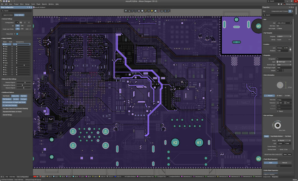
Altium Designer keyboard shortcuts
Altium Designer
Suggestion: This program has lots of (800) shortcuts. Try our shortened list of
20 basic Altium Designer shortcuts if you just want to get started.
This shortcut list is sorted by user, meaning that original structure (headings) is disregarded. You can see the original page here:
Altium Designer keyboard shortcuts.
Table of contents
Advertisement
Program information
Program name:

Web page: altium.com
How easy to press shortcuts: 84%
More information >>Featured shortcut
Similar programs
Tools
Altium Designer:Learn: Jump to a random shortcut
Hardest shortcut of Altium Designer
Other


What is your favorite Altium Designer hotkey? Do you have any useful tips for it? Let other users know below.
1106799
498270
411259
366077
306918
277367
23 hours ago
Yesterday
Yesterday
1 days ago
1 days ago Updated!
2 days ago Updated!
Latest articles