|
|
Cancel current command |
||
|
|
ERASE / Removes objects from a drawing. |
||
|
|
REDRAW / Refreshes the display in the current viewport. |
||
|
|
FILLET / Rounds and fillets the edges of objects. |
||
|
|
STRETCH / Stretches objects crossed by a selection window or polygon. |
||
|
|
CIRCLE / Creates a circle. |
||
|
|
ARC / Creates an arc. |
||
|
|
DIMSTYLE / Creates and modifies dimension styles. |
||
|
|
MTEXT / Creates a multiline text object. |
||
|
|
MOVE / Moves objects a specified distance in a specified direction. |
||
|
|
WBLOCK / Writes objects or a block to a new drawing file. |
||
|
|
Display Help |
||
|
|
EXPLODE / Breaks a compound object into its component objects. |
||
|
|
Copy object |
||
|
|
ZOOM / Increases or decreases the magnification of the view in the current viewport. |
||
|
|
VIEW / Saves and restores named views, camera views, layout views, and preset views. |
||
|
|
Toggle Isoplane |
||
|
|
Toggle text screen |
||
|
|
Undo last action |
||
|
|
Paste object |
||
|
|
INSERT / Inserts a block or drawing into the current drawing. |
||
|
|
PAN / Adds a parameter with grips to a dynamic block definition. |
||
|
|
BLOCK / Creates a block definition from selected objects. |
||
|
|
GROUP / Creates and manages saved sets of objects called groups. |
||
|
|
LINE / Creates straight line segments. |
||
|
|
HATCH / Fills an enclosed area or selected objects with a hatch pattern, solid fill, or gradient fill. |
||
|
|
Toggle object snap mode |
||
|
|
Toggle running object snaps |
||
|
|
Cut object |
||
|
|
OFFSET / Creates concentric circles, parallel lines, and parallel curves. |
||
|
|
Redo last action |
||
|
|
JOIN / Joins similar objects to form a single, unbroken object. |
||
|
|
Cycle isometric planes |
||
|
|
Toggle snap mode |
||
|
|
Toggle grid mode |
||
|
|
Toggle Grid |
||
|
|
Toggle ortho mode |
||
|
|
Toggle object snap tracking |
||
|
|
Toggle polar mode |
||
|
|
Toggle Pick Style |
||
|
|
Toggle dynamic input mode |
||
|
|
Property Palette |
||
|
|
Copy to clipboard with base point |
||
|
|
Design Center Palette |
||
|
|
Clean Screen |
||
|
|
Paste data as block |
||
|
|
Tool Palette |
||
|
|
Sheet Set Palette |
||
|
|
Toggle display palettes |
||
|
|
Cancel current command |
||
|
|
Quick Calc |
||
|
|
Command Line |
||
|
|
Markup Set Manager Palette |
||
|
|
Cancel current command |
||
|
|
GRADIENT / Fills an enclosed area or selected objects with a gradient fill. |
||
|
|
AREA / Calculates the area and perimeter of objects or defined areas. |
||
|
|
MIRROR / Creates a mirrored copy of selected objects. |
||
|
|
OSNAP / Sets running object snap modes. |
||
|
|
SCALE / Enlarges or reduces selected objects, keeping the proportions of the object the same after scaling. |
||
Advertisement |
|||
|
|
STYLE / Creates, modifies, or specifies text styles. |
||
|
|
TRIM / Trims objects to meet the edges of other objects. |
||
|
|
MATCHPROP / Applies the properties of a selected object to other objects. |
||
|
|
CTABLESTYLE / Sets the name of the current table style. |
||
|
|
BSAVE / Saves the current block definition. |
||
|
|
DIST / Measures the distance and angle between two points. |
||
|
|
DRAWORDER / Changes the draw order of images and other objects. |
||
|
|
LAYOUT / Creates and modifies drawing layout tabs. |
||
|
|
ARRAY / Creates multiple copies of objects in a pattern. |
||
|
|
ROTATE / Rotates objects around a base point. |
||
|
|
SNAP / Restricts cursor movement to specified intervals. |
||
|
|
SOLID / Creates solid-filled triangles and quadrilaterals. |
||
|
|
SPELL / Checks spelling in a drawing. |
||
|
|
PASTESPEC / Pastes objects from the Clipboard into the current drawing and controls the format of the data. |
||
|
|
MSPACE / Switches from paper space to a model space viewport. |
||
|
|
MVIEW / Creates and controls layout viewports. |
||
|
|
PCINWIZARD /Displays a wizard to import PCP and PC2 configuration file plot settings into the Model or current layout. |
||
|
|
PLINE / Creates a 2D polyline. |
||
|
|
POINT / Creates a point object. |
||
|
|
MTEXT / Creates a multiline text object. |
||
|
|
REVCLOUD /Creates or modifies a revision cloud. |
||
|
|
REGEN / Regenerates the entire drawing from the current viewport. |
||
|
|
PROPERTIES / Displays Properties palette. |
||
|
|
PSPACE / Switches from a model space viewport to paper space. |
||
|
|
SUBTRACT / Creates a new region by subtracting one overlapping region from another. |
||
|
|
OPTIONS / Customizes the program settings. |
||
|
|
ALIGN / Aligns objects with other objects in 2D. |
||
|
|
MEASURE / Creates point objects or blocks at measured intervals along the length or perimeter of an object. |
||
|
|
LIST / Displays property data for selected objects. |
||
|
|
ELLIPSE / Creates an ellipse or an elliptical arc. |
||
|
|
EXTERNALREFERENCES / Opens the External References palette. |
||
|
|
PROPERTIES / Controls properties of existing objects. |
||
|
|
BREAK / Breaks the selected object between two points. |
||
|
|
BCLOSE / Closes the Block Editor. |
||
|
|
BEDIT / Opens the block definition in the Block Editor. |
||
|
|
HATCH / Fills an enclosed area or selected objects with a hatch pattern, solid fill, or gradient fill. |
||
|
|
BOUNDARY / Creates a region or a polyline from an enclosed area. |
||
|
|
COPY / Copies objects a specified distance in a specified direction. |
||
|
|
TEXT / Creates a single-line text object. |
||
|
|
QLEADER / Creates a leader and leader annotation. |
||
|
|
INTERSECT / Creates a 2D region object from the overlapping area of two or more existing regions. |
||
|
|
LAYER / Manages layers and layer properties. |
||
|
|
XBIND / Binds one or more definitions of named objects in an xref to the current drawing. |
||
|
|
XCLIP / Crops the display of a selected external reference or block reference to a specified boundary. |
||
|
|
TABLE / Creates an empty table object. |
||
|
|
TOOLPALETTES / Opens the Tool Palettes window. |
||
|
|
RECTANG / Creates a rectangular polyline. |
||
|
|
PROPERTIES / Controls properties of existing objects. |
||
|
|
POLYGON / Creates an equilateral closed polyline. |
||
|
|
PEDIT / Edits polylines, objects to be joined to polylines and related objects. |
||
|
|
QUICKPROPERTIES / Displays open drawings and layouts in a drawing in preview images. |
||
|
|
THICKNESS / Sets the default 3D thickness property when creating 2D geometric objects. |
||
|
|
TEXTALIGN / Aligns multiple text objects vertically, horizontally, or obliquely |
||
|
|
SETVAR / Lists or changes the values of system variables. |
||
|
|
SPLINE / Creates a smooth curve that passes through or near specified points. |
||
|
|
XREF / Starts the EXTERNALREFERENCES command. |
||
|
|
TABLESTYLE / Creates, modifies, or specifies table styles. |
||
|
|
UCSMAN / Manages defined user coordinate systems. |
||
|
|
UNITS / Controls coordinate and angle display formats and precision. |
||
|
|
XATTACH / Inserts a DWG file as an external reference (xref). |
||
|
|
INSERTOBJ / Inserts a linked or embedded object. |
||
|
|
LWEIGHT / Sets the current lineweight, lineweight display options, and lineweight units. |
||
|
|
SAVEAS / Saves the current drawing. |
||
|
|
DSETTINGS / Sets grid and snap, polar and object snap tracking, object snap modes, Dynamic Input, and Quick Properties. |
||
|
|
EXTEND / Extends objects to meet the edges of other objects. |
||
|
|
HIDE / Regenerates a 3D wireframe model with hidden lines suppressed. |
||
|
|
DIVIDE / Creates evenly spaced point objects or blocks along the length or perimeter of an object. |
||
|
|
DATALINK / The Data Link dialog box is displayed. |
||
|
|
DATALINKUPDATE / Updates data to or from an established external data link. |
||
|
|
DONUT / Creates a filled circle or a wide ring. |
||
|
|
DIMORDINATE / Creates ordinate dimensions. |
||
|
|
DIMOVERRIDE / Controls overrides of system variables used in selected dimensions. |
||
|
|
DIMRADIUS / Creates a radius dimension for a circle or an arc. |
||
|
|
DIMREASSOCIATE / Associates or re-associates selected dimensions to objects or points on objects. |
||
|
|
DRAWINGRECOVERY / Displays a list of drawing files that can be recovered after a program or system failure. |
||
|
|
DIMJOGLINE / Adds or removes a jog line on a linear or aligned dimension. |
||
|
|
DIMJOGGED / Creates jogged dimensions for circles and arcs. |
||
|
|
CHAMFER / Bevels the edges of objects. |
||
|
|
COMMANDLINE / Displays the Command Line window. |
||
|
|
COLOR / Sets the color for new objects. |
||
|
|
BVSTATE / Creates, sets, or deletes a visibility state in a dynamic block. |
||
|
|
CONSTRAINTBAR / A toolbar-like UI element that displays the available geometric constraints on an object. |
||
|
|
DIMANGULAR / Creates an angular dimension. |
||
|
|
DIMARC / Creates an arc length dimension. |
||
|
|
DIMBASELINE / Creates a linear, angular, or ordinate dimension from the baseline of the previous or selected dimension. |
||
|
|
DIMCENTER / Creates the center mark or the centerlines of circles and arcs. |
||
|
|
DIMCONTINUE / Creates a dimension that starts from an extension line of a previously created dimension. |
||
|
|
DIMDISASSOCIATE / Removes associativity from selected dimensions. |
||
|
|
DIMDIAMETER / Creates a diameter dimension for a circle or an arc. |
||
|
|
DIMEDIT / Edits dimension text and extension lines. |
||
|
|
ID / Displays the UCS coordinate values of a specified location. |
||
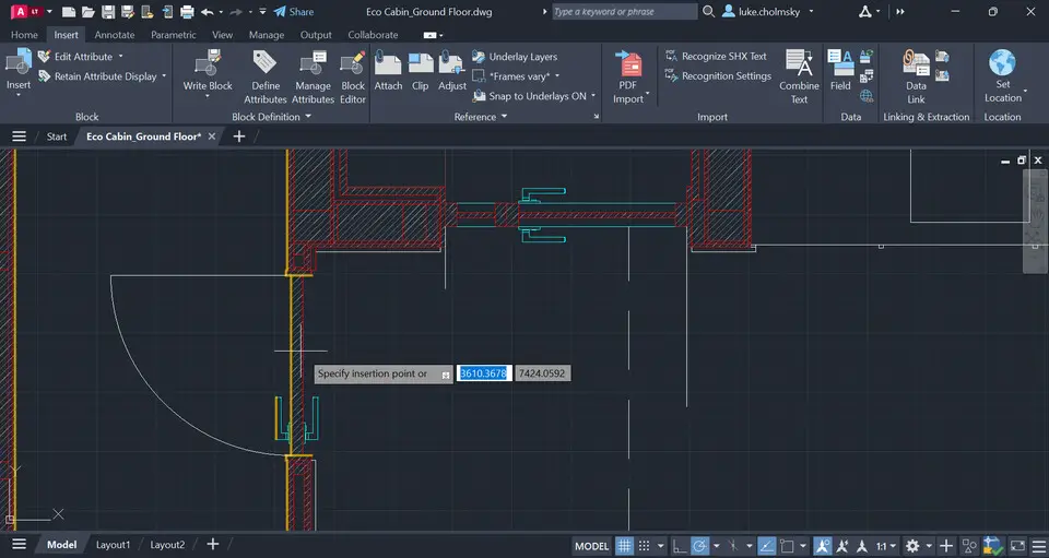
AutoCAD LT (2024) keyboard shortcuts
AutoCAD LT (2024)
This shortcut list is sorted by user, meaning that original structure (headings) is disregarded. You can see the original page here:
AutoCAD LT (2024) keyboard shortcuts.
Table of contents
Advertisement
Program information
Program name:

Web page: autodesk.com/products/autocad-...
How easy to press shortcuts: 64%
More information >>Similar programs
Tools
AutoCAD LT (2024):Learn: Jump to a random shortcut
Hardest shortcut of AutoCAD LT (202...
Other


What is your favorite AutoCAD LT (2024) hotkey? Do you have any useful tips for it? Let other users know below.
1108032
498772
411518
366987
307454
277921
8 hours ago
14 hours ago
Yesterday Updated!
2 days ago Updated!
2 days ago
3 days ago
Latest articles