|
|
AUTOMATIC CONTACTS / Compares automatic contacts. |
||
|
|
BOUNDARY CONDITIONS / Toggles display of all boundary conditions. |
||
|
|
BEARING LOAD / Applies a bearing load to a full or partial cylindrical surface. BO BODY LOAD / Defines angular velocity or angular or linear acceleration for the model. |
||
|
|
COLOR BAR / Displays the Color Bar settings dialog box where you adjust the color bar display parameters. CF FIXED CONSTRAINT / Applies a fixed constraint on selected faces, edges, or vertices. |
||
|
|
CONVERGENCE PLOT / Displays the plot within a dialog box.* |
||
|
|
PIN CONSTRAINT / Sets the pinned constraint origin and offset.* |
||
|
|
FRICTIONLESS CONSTRAINT / Applies a frictionless constraint on selected faces. |
||
|
|
CONTOUR SHADING / Displays color changes using a strict banding between colors. |
||
|
|
FORCE LOAD / Applies a force of the specified magnitude to the selected faces, edges, or vertices. |
||
|
|
GRAVITY LOAD / Creates a gravity load. |
||
|
|
ASSIGN MATERIALS / Opens the assign materials dialogue box to assign materials to a component. |
||
|
|
MAXIMUM RESULT / Turns on and off the display of the point of maximum result in the mode. |
||
|
|
MANUAL CONTACT / Adds manual contact conditions to selected geometry elements. |
||
|
|
MINIMUM RESULT / Turns on and off the display of the point of minimum result in the model. |
||
|
|
LOCAL MESH CONTROL / Adds a local mesh control. |
||
|
|
MOMENT LOAD / Applies a load of the specified magnitude around the axis and perpendicular to the face. |
||
|
|
MESH SETTINGS / Specifies the mesh sizing and coarseness. |
||
|
|
MESH VIEW / Displays the element mesh used in the solution with the result contours. Also displays the mesh over the undeformed model. |
||
|
|
CREATE SIMULATION / Creates new simulation. |
||
|
|
NO SHADING / Turns off the Shaded Results display. |
||
|
|
PROBE / Activates the Probe command. You place probes as needed in areas of interest to display the stress values for that point. |
||
|
|
PROBE LABELS / Toggles the visibility of probe labels. |
||
|
|
PRESSURE LOAD / Pressure load. |
||
|
|
REPORT / Generates a report. |
||
|
|
REMOTE FORCE LOAD / Applies a force of the specified magnitude to the selected face. |
||
|
|
SIMULATE / Runs a simulation. |
||
|
|
RESULT DISPLACEMENT SCALE / Adjusts displacement scale. SET STRESS ANALYSIS SETTINGS / Activates the stress analysis settings dialog box. |
||
|
|
SMOOTH SHADING / Displays color changes using a blended transition. |
||
|
|
SAME SCALE / Maintains the same scale while viewing different results. |
||
|
|
PARAMETRIC TABLE / Accesses the parametric table to specify design constraints and parameter ranges. |
||
|
Tools
|
|||
|
|
EDIT LAYERS / Specifies a layer name and attributes for common display properties of drawing objects. |
||
|
|
MEASURE DISTANCE / Opens the Measure Distance window. |
||
|
|
APPLICATION OPTIONS / Opens the Application Options settings. |
||
|
|
EDIT STYLES / Style and Standard Editor. |
||
|
Tube & Pipe
|
|||
|
|
TUBE & PIPE AUTHORING / Authors an iPart or a normal part for publishing to the Content Center Library. |
||
|
|
CONNECT FITTINGS / Connects existing fittings. |
||
|
|
DERIVED MOTION / Creates or edits a derived route. |
||
|
|
EDIT BASE SKETCH / Edits the base 3D sketch. |
||
|
|
HOSE LENGTH / Edits hose length by changing end tangency weights. |
||
|
|
INCLUDE GEOMETRY / Introduces reference geometry to the route sketch. |
||
|
|
INSERT NODE / Inserts route node into segment. |
||
|
|
ISOGEN OUTPUT / Saves a file with a specified name and ISOGEN file type. |
||
|
|
MOVE NODE / Drags node to a new location. |
||
|
|
MOVE SEGMENT / Drags segment to a new location. |
||
|
|
NEW ROUTE / Adds new rigid piping and bent tubing routes to a pipe run. |
||
|
|
PLACE FITTING / Picks up a fitting from your project work space to place into the active run. |
||
|
|
CREATE PIPE RUN / Creates pipe run.* |
||
|
|
POPULATE ROUTE / Populates route.* |
||
|
|
ROUTE / Starts or continues route definition. |
||
|
|
TUBE AND PIPE STYLES / Copies and modifies existing style definitions and delete styles you no longer use. |
||
|
|
GROUNDED WORK POINT / Grounded Work Point. |
||
|
View
|
|||
|
|
FREE ORBIT / Rotates a model about the center of the screen or about axes in model space. |
||
|
|
PAN / Pans the view. |
||
|
|
VIEWCUBE / Toggles the view of the ViewCube. |
||
|
|
ZOOM WINDOW / Zooms in on a specified area. |
||
|
Source: Autodesk
|
|||
Autodesk Inventor (2022) keyboard shortcuts
Autodesk Inventor (2022)
Table of contents
Advertisement
Program information
Program name:
![]()
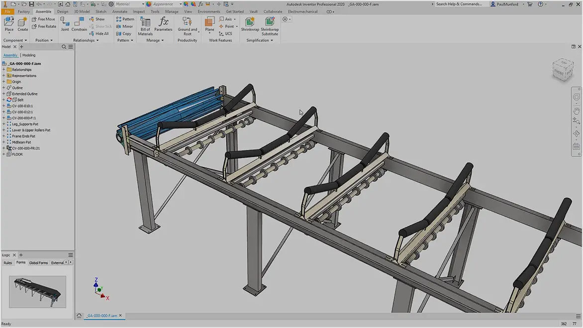
Autodesk Inventor is a computer-aided design software for 3D mechanical design, simulation, visualization, and documentation. Autodesk Inventor includes parametric, direct edit and freeform modeling tools as well as multi-CAD translation capabilities.
Web page: autodesk.com/products/inventor...
How easy to press shortcuts: 67%
More information >>
Updated: Added some shortcuts.
(2 updates.)
6/28/2022 10:23:19 PM New program added.
6/28/2022 10:25:23 PM Added some shortcuts.
Shortcut count: 331
Platform detected: Windows or Linux
Other languages:
Similar programs
Tools
Autodesk Inventor (2022):Learn: Jump to a random shortcut
Hardest shortcut of Autodesk Invent...
Other
What is your favorite Autodesk Inventor (2022) hotkey? Do you have any useful tips for it? Let other users know below.
1065479 168
480660 7
399833 370
334432 6
284959 5
263619 31
2 days ago
3 days ago
4 days ago
5 days ago Updated!
8 days ago
10 days ago
Latest articles
How to delete a stubborn folder ending with space
When did WASD keys become standard?
How I solved Windows not shutting down problem